
WT-900: an integrated Ultrasonic station for weld inspection
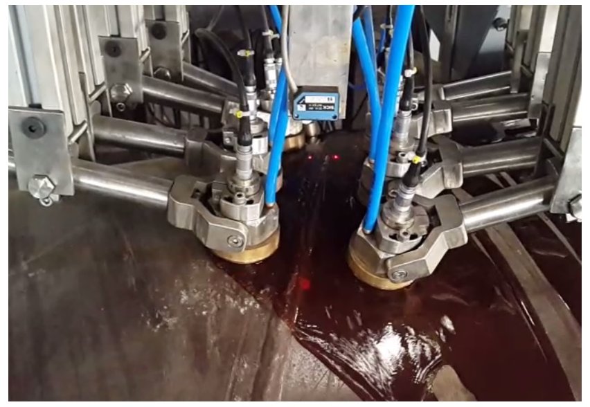
WT-900 is an integrated ultrasonic station for in line weld inspection. Especially of interest for tube and pipe manufacturers requiring UT testing immediately after the welding process.
The system is built around 4 channel pulser receiver modules, each individually capable to sequentially test in puls-echo for direct flaw detection and through transmission for coupling check. The same modules can also be set up for wall thickness testing and delamination testing (HAZ).
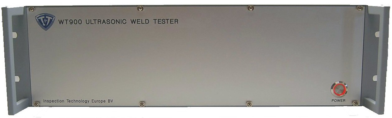
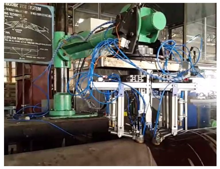
front view WT-900
Configuration
The WT-900 is based on the MFD900 technology and software and is special configured for multiplexed applications such as ultrasonic weld testing.
The standard unit contains 12 channels of which 2 chanels are used for internal ( ID) longitudinal weld defects, 2 channels for external (OD) longitudinal weld defects, 4 channels are set up for transverse defects, and the other channels can be used for delamination detection in the heat affected zone (HAZ) and thickness measurement.
The system is built in a 3HE high 19″ rack unit and can be controlled from any PC through an ethernet cable.
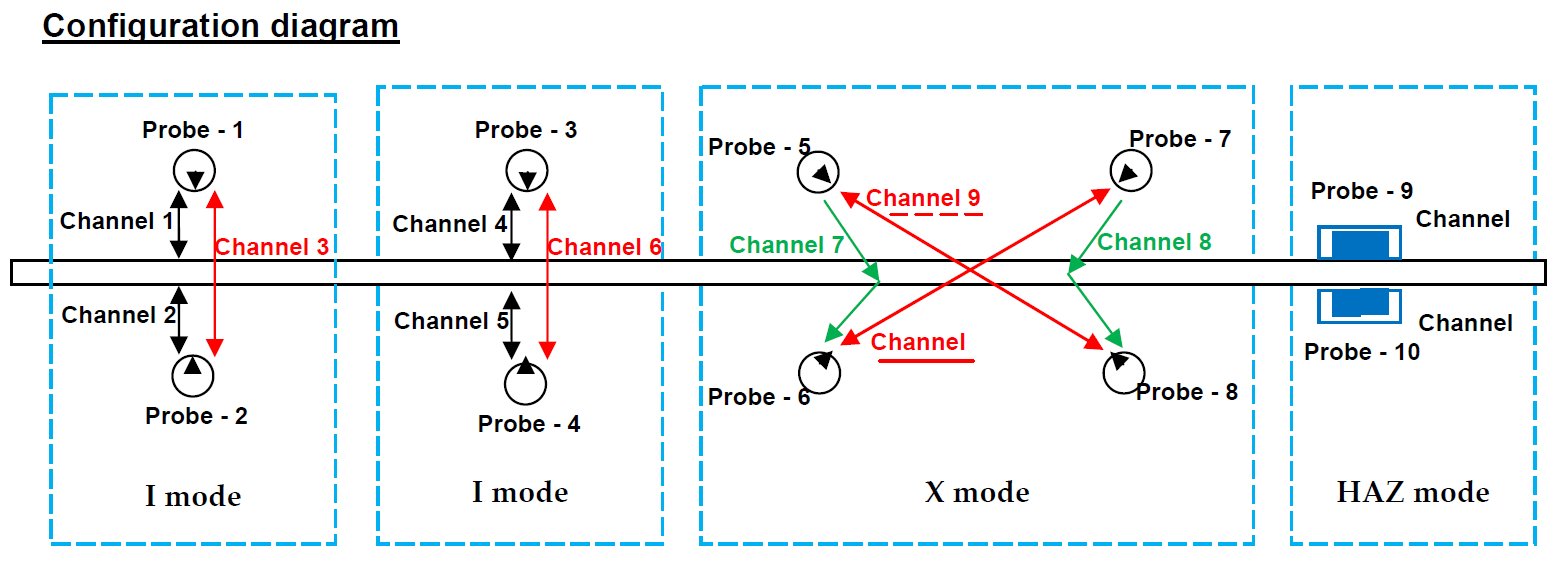
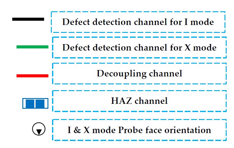

Up to 5 modules of 4 channels each can be placed in the system, resulting in a 20 channel ultrasonic inspection system. A typical configuration for weld testing with detection of longitudinal defects, transverse defects and wall thickness can be as shown in above diagram.
Key features
The instrument features up to 999 program locations to store inspection settings .
- Easy operation by PC mouse control
- Each channel equipped with 2 flaw gates with analog peak detectors, alarm logic and gated amplifier
- Selective attenuation and gain on each gate
- One water path meter and one universal thickness meter available on each channel
- Segmented TCG on each channel
- PRF per channel = 20 kHz/number of scan tabel entries
- 2 encoder inputs for in line production testing and displaying real time graphics
- Industrial I/O and PLC interface
- High speed real time analog and alarm output option
- Position programmable paint marker output
- Ethernet and RS232 interface
- Standard interface for external hardware, such as sorters/alarm/ PLC /data processing equipment
- 4 user levels. Each user level can be set to allow certain features to be operated
- Powerful recording and reporting software
- On-line /Real-time support by the internet with Team Viewer !
Recording and reporting
The WT-900 software allows for building up individual recordings of the various ultrasonic test results. Simply select the ultrasonic channel and the gate and you can plot another graph

Operator at work
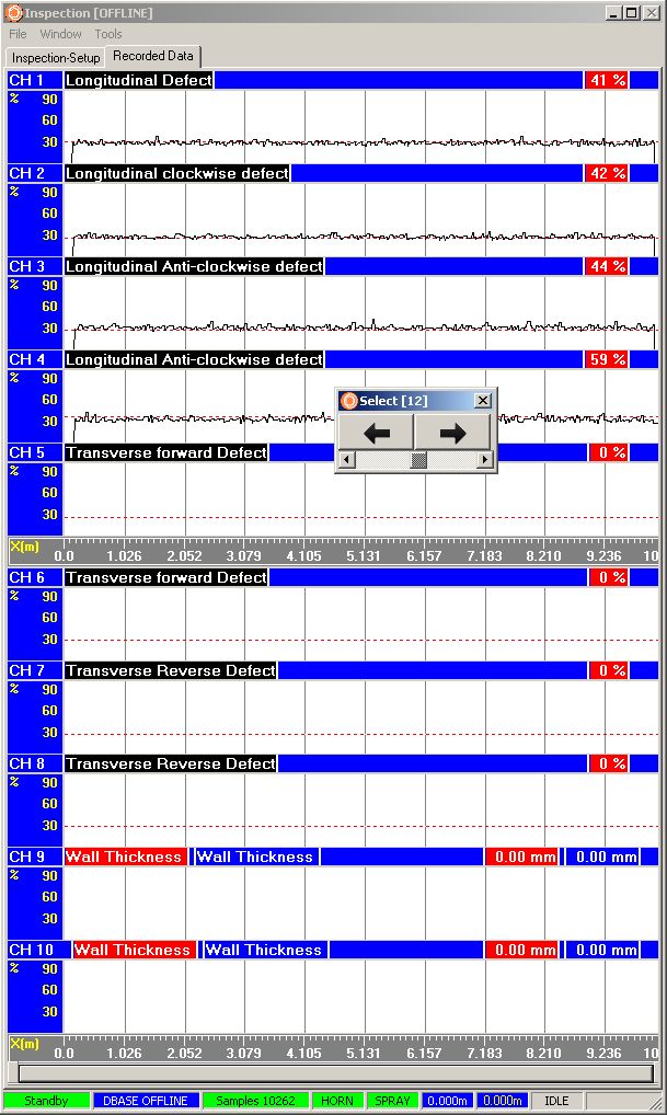
User defined graphs
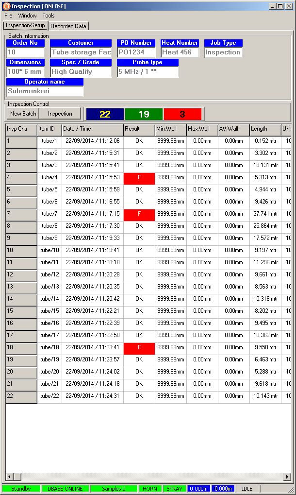
User defined reporting
Technical specifications
- Supply voltage : 90.. 240V (internally selectable)
- Supply voltage tolerance : 190..240V / 80..120V AC 50/60Hz
- Power consumption : max. 250W (10 channels installed)
- Dimensions : 450 x 570 mm (WXHXD) 19 inch 3U
- Weight : 6 kg
- Construction : Plug in modules
- PC Interface : Gigabit Ethernet UDP/IP Protocol with error correction
- System interface : 16 bits bus for data, 16 bits bus for settings
- External : 16 Inputs, 16 Outputs (1=dedicated fast alarm output)
- Encoders : 2, quadrature or clock / direction 4 x resolution in quadrature mode
- Encoder freq. : 2 MHz maximum
- Remote I/O : RS485 / High Speed Output
- Options : Real Time Output unit
- Trigger : Input / output via BNC with frequency limit, TTL level
Brochure
Pulser Receiver PRU924 Specifications
- TOF : 2, measuring between IP and IF echo (water path)
- Measuring between 2 echoes in the gate,
- Noise blanking and zero crossing detection (Thickness gauge)
- TOF Clock : 50 MHz (TOF1) / 160 MHz (TOF2)
- Detector : 2 Digital peak detectors @ 100 MHz (150 MHz optional)
- Flaw gates : 2, each with peak detector, alarm logic and gated amplifier
- Alarm : OFF, POS, NEG
- Alarm filter : 1..200 (consecutive alarms)
- Interface : Via dedicated interface gate
- Gate Trigger : OFF, IP/IF/ARTIF
- Connectors : BNC
- Gain control : -10 .. +90 dB
- Bandwidth : 100 KHz .. 30MHz (-6/-6 dB)
- Filters : HPF (Off, 1MHz, 2.5MHz, 5MHz) @ 12dB/oct
- BPF (Off, 1MHz, 2.25MHz, 5MHz, 7.5MHz, 10MHz 15MHz, 25MHz) 100% bandwidth
- LPF (Off, 5MHz, 10MHz, 20MHz) 24dB/oct
- Output : RF, HW-, HW+, FW, FW+F1, FW+F2, Fw+ F3
- Input impedance : 50 Ohm / 1 kOhm selectable in through transmission modes
- Linearity : Better than 1% of full scale
- Eq. Input Noise : 50uV RMS (10KHz .. 50MHz)
- Gated Gain : -20 .. +20dB
- TCG Type : Segmented with 16 segments Control Range : -20 .. +50 dB
- Pulser Specifications (A/B Pulser)
- Output : Negative Square wave
- Connector : BNC
- Width : 25 .. 500 ns adjustable in 1 ns steps
- Voltage : -50 .. -350 V
- Fall time : < 10 ns (-200V pulse)
- Rise time : <15 ns (Damping 50 Ohm, no load, -200V pulse)
- Impedance : <10 Ohm
- Repetition Rate : max 10 kHz, adjustable per pulser
- Damping Range : 25 .. 315 Ohm in 5 Ohm steps