Measuring nodularity of cast iron for in-line applications and fast sample testing
ITE-Model 2 nodularity tester uses ultrasound to determine the propagation speed of ultrasonic sound in cast iron products or samples. Measuring the velocity of sound in cast iron is a general accepted method to determine the nodularity and also as an early warning system in a continuous process in case the nodularity deviates from a standard .
To determine the sound speed, the product thickness must first be exactly measured. Then an ultrasound signal is sent through the casting sample and the travel time is measured. The sound speed (in meters or inches per second) can be calculated from the thickness and travel time of the sound in the product. (Velocity = Meter/second (or inches/second) )
There are different methods to measure the velocity. The most basic method is to measure the thickness manually with a caliper. With a simple hand held ultrasonic Velocity meter you feed in the product thickness, measure the sample and the instrument immediately tells you the Velocity of the material. In fact this is a reversed ultrasonic thickness gauge.
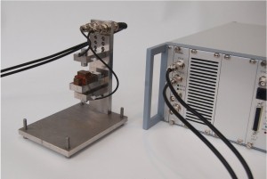
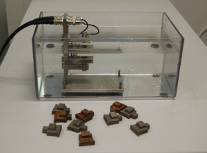
ITE-Model 2 was designed for large volume inspections and quick laboratory tests to avoid the time consuming chemical and optical sample analysis. To measure the thickness quickly and without physical contact with ultrasonic sensors (transducers), two ultrasonic sensors are positioned exactly opposite each other in a water bath. Water or any other fluid is required because this high-frequency ultrasonic sound cannot pass through air properly. With these two transducers the thickness of the block can be measured very quickly and immediately afterwards the sound speed. The number of measurements of the system is about 500 measurements per second, so for the user everything is immediately visible.
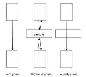
Principle:
- At the start of the process one transducer sends a signal through the water to the opposite transducer in order to exactly measure the time/ distance between the two.
- Then the sample is placed in between the transducers (manually or automated)
- Both transducers send out a signal which reflect back from the product surface to the respective transducer. From above derived measurements the system can now calculate the product thickness.
- Next, with the sample still in between the two transducers one transducer sends a signal through the water and material sample which is received by the opposite transducer
- The time difference between water only and with a sample in between, together with the calculated thickness of the sample can be used to calculate the velocity of the sound in the cast sample. This value is immediately displayed on a monitor.
Using this system, two steps must be taken in preparation:
Zeroing /determining the distance between the transducers and calibration with a reference sample of exact known thickness.
Important: Samples must have reasonable smooth but parallel surfaces. If the sample surface is not exactly perpendicular to the sound puls, the sound pulse is deviated and lower performance is the end result.
For mass production often a small sub part is casted which is cut off from the casting and which is used for analysis. These small parts can be easily tested with the accessory tool which is made for a small water tank.
Depending on the thickness the transducers can be positioned a different distance.
For in line applications at least a part of the product must be suitable to carry out this measurement including proper positioning in relation to the two transducers so the principle can be applied. Additional mechanical handling with be required.
Transducers can be made in various frequencies, diameters, focussed or not, all depending on the application.
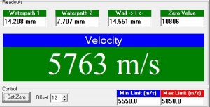
On the monitor a window as below is seen: It shows both water paths (only as indicative information) , the calculated thickness and in the middle the calculated sound velocity of the sample . High and low alarm is possible for external alarm.
——————————————————————————————————————-
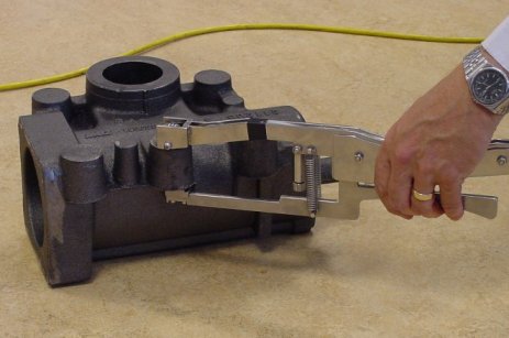
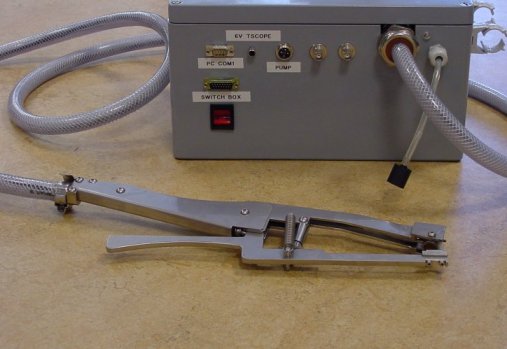
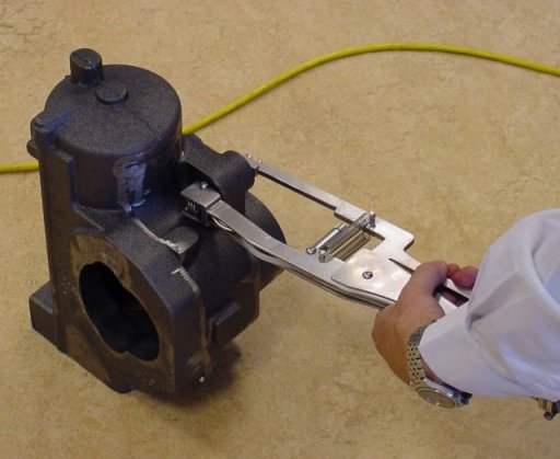
Solution for manual testing larger serie with complex shape. Mechanical caliper with ultrasound transducer built in
Determination of the sound velocity can be done manually with a simple ultrasonic gauge and a mechanical caliper. With a mechanical caliper the thickness is measured and at the same spot the ultrasonic time of flight is measured by simply placing a transducer ( probe) on the material using a little coupling fluid. The ultrasonic gauge measures the time which is needed for a short ultrasonic puls to travel through the product, bounce bach at the rear side and received back into the pobe . Same like a typical sonar system. The materials sound velocity V can then be calculated . V = thickness/ time of flight in meter/second or inches/second Inspection Technology Europe BV has developed a practical tool to carry out this measurement quick, with minimum effort and accurate. The systems grip contains a caliper which mechanically measures the thickness of the product and with an automatic water supply system the ultrasonic probe in the tip of the caliper is acoutically coupled. Ultrasonic coupling can also be done with conventional couplant gel without using water supply.
ultrasonic measurement of nodularity
The result shows the sound velocity which is immediately visible on a display and the user can set the alarm limits for accept / not accept measurements and optionally store the data in a database.